Charge Air Cooler (Standalone)
A standalone charge air cooler sits outside the engine block on a separate skid or in the funnel casing, cooling turbocharger discharge air before it reaches the cylinders, and is chosen when engine-room access, maintenance space or a shared cooling circuit favour a remote unit.
Read more — Charge Air Cooler (Standalone) explained ▾
What sets a standalone charge air cooler apart
Most medium and low-speed engines carry their charge air cooler bolted directly to the engine block, sharing its support structure and cooling water connections with the engine itself. A standalone unit is physically separated: mounted on its own skid, in a side casing, or remote in the funnel trunk, connected to the engine by air ducting rather than a shared flange. This is chosen when engine access for piston or liner overhaul would be blocked by an integrated cooler, or when one central cooler serves more than one engine, such as auxiliary generator sets sharing a single low-temperature cooling water circuit.
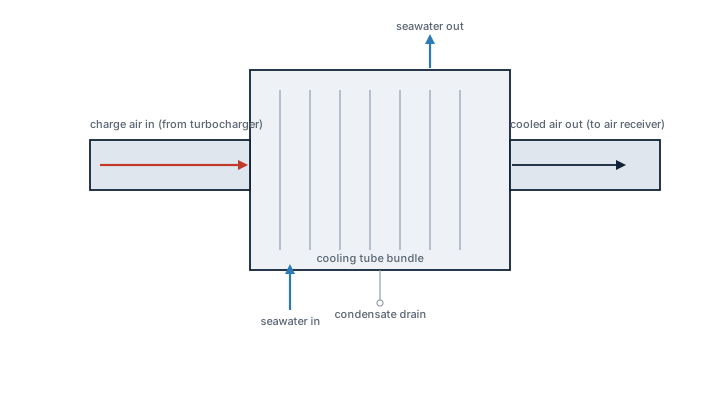
Main components
Tube or plate bundle
Finned tube bundles are the dominant design, with seawater or low-temperature freshwater on the tube side and compressed charge air on the shell side. Tube material is typically cupro-nickel or titanium where seawater cooling is used directly, since charge air coolers see continuous condensation and are prone to pitting.
Condensate collection
As hot, moist charge air cools, water condenses out of it. A standalone cooler needs its own drain trough and condensate trap, separate from the engine's own drain arrangement, to stop condensate carrying into the cylinders and washing lubricating oil off the liner.
Casing and ducting
Ducting runs from turbocharger outlet to cooler inlet and from cooler outlet to the engine air receiver. Expansion joints absorb thermal movement and must be inspected for leaks, since even a small air leak here bypasses the cooler and raises charge air temperature at the receiver.
Selection and sizing
Sizing follows the engine's rated air mass flow and required charge air temperature at the receiver, not the cooler's physical size alone. Key figures are approach temperature between cooling water inlet and air outlet, tube-side water velocity, and allowable air-side pressure drop, since excess pressure drop directly costs engine efficiency and raises exhaust temperature.
Regulations and class
There is no dedicated SOLAS chapter for charge air coolers, but class rules require the cooler to be included in the engine's periodic survey scope, and any repair affecting the pressure boundary between the water and air sides needs class approval, since a tube failure lets cooling water into the charge air path and can cause waterhammer in a running cylinder.
Typical faults
- Tube fouling from seawater scale or biofouling — cause: infrequent cleaning or poor water treatment; consequence: rising charge air temperature and falling engine efficiency
- Tube pitting and through-wall leaks — cause: erosion-corrosion at tube inlets or stray current; consequence: water ingress into the air side and possible waterhammer in a cylinder
- Condensate carryover — cause: blocked or undersized drain trough; consequence: oil dilution and accelerated liner wear
- Fin blockage on the air side — cause: oil mist or exhaust soot deposits; consequence: increased pressure drop and reduced boost
What to look for in a supplier
- Tube material proven against the ship's actual seawater cooling regime, not a generic cupro-nickel default
- Accessible tube bundle for pulling and hydraulic testing without major ducting removal
- Documented approach temperature and pressure drop curves at service and fouled conditions
- Condensate drain sized for tropical, high-humidity operation, not temperate-climate assumptions
A charge air cooler that seems to be cooling fine on the gauge can still be leaking, so track condensate drain quantity against expected humidity load, because a slow tube leak often shows up first as extra water in the drain, not as a temperature alarm.
Typical Manufacturers
3 manufacturers · 3 models
Alfa Laval
1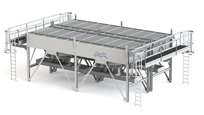
- Design Pressure M-Line
- >10 bar (145 psi)
- Marine Engine Room Modelle
- T6 (DN60, 800 kW) bis T35 (DN350, 35.000 kW)
- Marine FSRU Modelle
- TS45, T45, T50 (DN450-500, 45.000-55.000 kW)
- Temperaturbereich Standard
- 0-180°C (je nach Modell)
- FSRU Temperaturbereich
- -50 bis 150°C
- Plattentypen
- Chevron, Gemini Doppelwand, FlexFlow™
- M-Line (High Pressure Series: M3, M6, M10, M15)
- T-Series (Industrial: T2, T5, T6, T8, T10, T20, T25)
- AQ-Series (HVAC: AQ1, AQ2, AQ3, AQ4, AQ10)
- Marine Line (Engine Room: T6-T35; FSRU: TS45, T45, T50)
- Baseline (Competitive Line)
- Hygienic Line (Premium)
- Area: Gasket-Verschleiß und -VersprödungCheck: Dichtungen visuell auf Risse, Verhärtung, Quellung und Verfärbung inspizieren; Material-Kompatibilität mit Prozessflüssigkeiten überprüfen; ClipGrip™ Befestigung kontrollieren. Alterungserscheinungen und Elastizitätsverlust sind Austausch-Indikatoren.
- Area: Anpress-Maß und Dichtheit (Tightening Dimension A)Check: A-Dimension gemäß Herstellerangaben mit Messschieber überprüfen (metallischer Kontakt erforderlich). Bolzen sauber halten und schmieren. Überdrehen vermeiden. Regelmäßiges Nachziehen nach Betriebsstunden durchführen. Bei zu niedriger A-Dimension Druckverlust und Leckage zu erwarten.
- Area: Fouling und Verkalkung auf PlattenoberflächenCheck: Druckdifferenz über Wärmetauscher überwachen (Anstieg deutet auf Ablagerungen hin). Wärmeleistung vs. Design-Wert prüfen. CIP-Intervalle nach Performance-Audits optimieren. Ablagerungen erzeugen höhere Pumpenleistung (Energieverschwendung bis 8.000 kWh/Jahr möglich).
- Area: Plattenkorrosion und Risse / DurchbrücheCheck: Nach Demontage Plattenoberflächen auf Lokalmessungen (pittings), Risse und Lochfraß inspizieren. Materialkompatibilität mit Prozessflüssigkeit überprüfen. Ermüdungsrisse besonders an Ecken und Übergängen beobachten. Bei Lochbildung ist Platte unwiederbringlich und muss ersetzt werden.
- Area: Drucktest und DichtigkeitsprüfungCheck: Nach Demontage und Reinigung Hydrostatic Test gemäß Datenblatt durchführen. Prüfdruck typischerweise 1,5× Betriebsdruck. Externe und interne Leckage an allen Anschlüssen und Plattenrändern überprüfen. Befund dokumentieren.
- Area: Plattensequenz und Ausrichtung (5-Punkt-Ausrichtung)Check: Nach Öffnung Plattenfolge und Honeycomb-Muster überprüfen (korrigierte Chevron-Patterns müssen alternieren). 5-Punkt-Alignment System für größere Units aktivieren/validieren. Versatz oder Fehlplatzierung führt zu Kurzschluss und reduziertem Wärmevortrag.
Typ-universelle Inspektionspunkte fuer Alfa Laval Gasketed Plate Heat Exchangers (GPHE) (Alfa Laval, 2026-06). Per-Modell-Specs nicht auto-gefuellt.
- High design pressure (>10 bar) suitable for modern turbocharged marine engines
- Modular series (M‑Line, T‑Series) allows sizing from 800 kW to >35 MW
- Compact footprint compared with shell‑and‑tube coolers, saving engine‑room space
- Multiple plate types (Chevron, Gemini double‑wall, FlexFlow™) provide fouling resistance and corrosion protection
- Standardised inspection points and easy gasket replacement simplify maintenance
- Gasket wear can lead to leakage; requires regular visual checks and periodic replacement
- Performance degrades with fouling; cleaning intervals must be managed carefully
- Maximum temperature limited to ~180 °C, restricting use in very high‑temperature cycles
- Tightening dimension (A‑dimension) is critical – improper torque can cause pressure loss or leaks
- Initial capital cost higher than basic shell‑and‑tube units
MAN Energy Solutions
1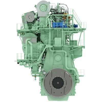
- Water leak into air side
- Corrosion from acidic condensate
- Gasket failure
- OEM‑matched to MAN engine families (12V, 16V, 28/32 series) ensuring optimal fit and performance
- High heat‑transfer efficiency with corrosion‑resistant stainless steel cores
- Compact, modular design that simplifies installation and replacement on existing vessels
- Low pressure drop across the exchanger, preserving engine boost pressure
- Standardised gasket and seal kit from MAN reduces risk of mismatched components
- Limited to MAN‑specified engines; not a universal fit for other manufacturers
- Potential water ingress if gaskets are not replaced with MAN‑approved parts
- Heavier than some aluminium‑based alternatives, affecting weight‑critical installations
- Requires strict coolant quality control to avoid acidic condensate corrosion
- Spare part availability tied to MAN supply chain; longer lead times in remote ports
Vestas
1
- Tube leakage
- Fin corrosion
- Reduced cooling from fouling
- Class‑survey pressure tested, meeting regulatory inspection requirements
- Removable fin design simplifies routine cleaning to mitigate fouling
- Compact single‑unit layout eases installation on existing engine rooms
- Reported tube leakage issues can lead to loss of cooling efficiency
- Fin corrosion observed in high‑humidity or salt‑laden environments
- Performance degrades noticeably if fins become fouled and are not cleaned regularly