Exhaust Gas Economizer
An exhaust gas economizer sits in the main engine exhaust uptake and raises steam from waste heat alone, without its own burner, which is what separates it from an oil-fired auxiliary boiler that makes steam on demand regardless of engine load.
Read more — Exhaust Gas Economizer explained ▾
What sets this type apart
An exhaust gas economizer is a heat exchanger, not a combustion boiler: exhaust gas from the main engine passes over a bank of finned tubes, and the heat it would otherwise vent to atmosphere raises steam or heats thermal oil instead. It has no burner of its own, so its steam output tracks main engine load directly. At low load or manoeuvring, exhaust temperature and flow drop and steam production falls with them, which is why most installations still keep an oil-fired auxiliary boiler for port stays and low-load conditions.

Main components
Tube bank
Finned steel tubes arranged for cross-flow of exhaust gas, sized to recover heat without imposing excessive backpressure on the main engine.
Steam drum
Collects generated steam and separates it from circulating water in a forced-circulation design, feeding the ship's steam services.
Circulation pump
Forced-circulation economizers use a pump to move water through the tube bank rather than relying on natural convection, giving more even heat transfer and less risk of local dry-out.
Soot blowers
Steam or compressed-air lances that periodically clear soot deposits from the tube surfaces; deposits are the single biggest threat to this equipment.
Water washing arrangement
Fixed piping for periodic fresh water washing of the tube bank, used at low load or in port when soot fires would otherwise be more likely.
Selection and sizing
Sizing is driven by main engine exhaust flow and temperature at normal sea speed, the steam demand the vessel actually needs to cover (cargo heating on tankers, fuel oil heating, accommodation services), and the allowable exhaust backpressure the engine maker permits. Oversizing the tube bank for heat recovery without checking backpressure can quietly cost fuel efficiency on the main engine itself.
Regulations and class
Class rules require periodic internal and external inspection of the pressure parts as a boiler, including the tube bank, drum and safety valves, on the same survey cycle as other steam-generating equipment. Fire risk from soot accumulation is addressed through class guidance on soot blower and water washing frequency rather than a fixed statutory interval, and MARPOL Annex VI exhaust temperature and backpressure limits from the main engine maker constrain how much fouling can be tolerated before cleaning is mandatory.
Typical faults
- Soot fire in the tube bank -- unburned fuel deposits accumulate and ignite from a hot spot; the consequence ranges from tube damage to a serious exhaust uptake fire if soot blowing has been skipped.
- Tube fouling from irregular soot blowing -- deposits build steadily; the consequence is falling steam output and rising exhaust backpressure that eats into main engine efficiency.
- Tube corrosion from sulphuric acid dew point -- running with cold feedwater below the acid dew point of the exhaust gas; the consequence is accelerated tube wall thinning and eventual leaks.
- Circulation pump failure -- loss of forced flow through the tube bank; the consequence is local overheating and tube damage if the unit is not shut down promptly.
What to look for in a supplier
- Tube bank material and fin design suited to the fuel sulphur content the vessel actually burns, not a generic low-sulphur assumption.
- Soot blower and water washing systems sized for the tube geometry supplied, with accessible lances for maintenance.
- Documented backpressure figures at the tube bank so the impact on main engine performance can be checked against the engine maker's limit.
- Spare tube sections or repair sleeves available without a long lead time, since tube leaks are the most common failure needing replacement parts.
Keep feedwater temperature above the acid dew point whenever the engine is running on higher-sulphur fuel -- cold feedwater is the quiet cause behind most premature tube corrosion, long before soot fires get the blame.
Typical Manufacturers
4 manufacturers · 18 models
Alfa Laval
10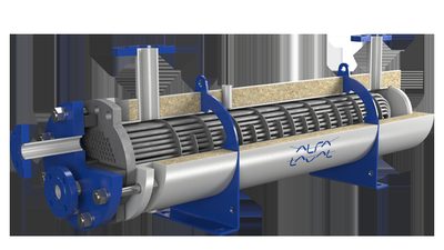
- Betriebsdruck (typisch)
- 5-30 bar(g), max. 65 bar(g)
- Design-Druck XS-TC7A
- 10 bar(g)
- Pinch Point
- 10-20°C (Minimum 5°C)
- Rohrbauart
- Rauchrohr (XS-Serie), Wasserrohr (AV-6N, XW), mit Rippen (gilled tubes)
- Zirkulation
- Natürlich (AV-6N Standard), Erzwungen (XW, Forced Circulation Optionen)
- Größe
- XS-TC7A: Kompakteste Rauchrohr-Economizer am Markt
- Materialien/fouling
- Helix-Rohre, vertikales Design mit hoher Gasgeschwindigkeit minimiert Verschlammung
- Aalborg XS-TC7A (Smoke-Tube Economizer)
- Aalborg AV-6N (Water-Tube Boiler, Natural Circulation)
- Aalborg XW / XW-TG (Water-Tube Economizer, Forced Circulation)
- Aalborg XS-2V / XS-7V (Smoke-Tube Economizers)
- Aalborg Micro (Compact Waste Heat Recovery)
- Aalborg H/HW (Waste Heat Recovery after Gas/Diesel Engines)
- Area: Rohrverschlammung / Rußabbrand-Gefahr (Soot Fouling)Check: Visual inspection of gas side for soot buildup, exhaust temperature measurement: >10-20°C above setpoint indicates sludging; perform water flushing kit application (50 l/min, 0.4-0.6 MPa pressure); operate Soot-Blower daily 3x (caution: In case of uptake fire DO NOT blow down with steam due to H₂ fire hazard)
- Area: Rohrleckage / Korrosion / Erosion (Tube Leakage)Check: Internal inspection test (opening of sight glasses/hand ports): inspect tubes for wear, pitting, thinning; external inspection for soot deposits, blistering, sag; perform hydraulic pressure test at 1.25 × operating pressure for maximum 10 minutes
- Area: Druckbehälter-Klassbesichtigung / Periodische InspektionCheck: Class surveyor: Inspect all boilers >3.5 bar working pressure and >4.65 m² heating surface. Frequency: DNV/LLOYDS every 2 years up to 8 years old, then annually; 2 comprehensive internal inspections per 5-year period, interval maximum 36 months. Inspect internal surfaces (drums, headers) for sludging, corrosion, cracks.
- Area: Sicherheitsventile / ÜberdruckschutzCheck: Safety valve test: opening at ≤3% above working pressure; test pressure 15% above working pressure for maximum 10 minutes (feedwater only for water level safety); pressure rise during test maximum 10% above design pressure at full load firing with stop valves closed.
- Area: Wasserspiegel-Schauglas / SchutzeinrichtungenCheck: Sight glass visual inspection for highest, lowest, normal water level markings; protective devices without sight obstruction; test water cushion safety ball valve for function; check drain line for safety.
- Area: Refractory / furnace room (only for fired boilers); tube bundle cleaning (XS-TC7A helix tubes)Check: For Aalborg OL/D and similar burner boilers: inspect refractory material (membrane walls, furnace floor) for cracks, deformation, separation; remove carbon deposits. For XS-TC7A: clean helix tube bundle with water flush kit (7–8 hours on similar ships), if necessary add cleaning chemicals before discharge to slop tank.
Type-universal inspection points for Alfa Laval Aalborg Exhaust Gas Boiler / Economizer (Aalborg + Class/eCFR, 2026-06). Per-model specs not auto-populated.
- Compact design – one of the smallest smoke‑tube economizers on the market
- Helix‑type tubes and high gas velocity minimise soot fouling
- Natural circulation eliminates the need for pumps or forced‑circulation systems
- Wide operating pressure range (5–30 bar, max 65 bar) suitable for many ship steam demands
- Low pinch point (10‑20 °C) improves overall heat‑recovery efficiency
- Maximum design pressure of 65 bar limits use on very high‑pressure steam systems
- Natural circulation may restrict maximum steam output compared with forced‑circulation models
- Requires diligent soot‑blowing and periodic tube cleaning to avoid fouling
- Less flexible for retrofits where space constraints are extreme (larger than micro‑WHR units)
- No built‑in fuel‑oil firing – solely dependent on exhaust gas availability

- Dampfkapazität OL
- 12.500–55.000 kg/h (mit BOG-Management)
- Dampfkapazität D
- 25–120 t/h (Tanker-Hauptkessel)
- Designdrücke
- 9 or 18 bar(g)
- Konstruktion
- Zweritrommel (Dampftrommel/Wassertrommel), Membranwände, Generatorröhrenbank
- Rohrsystem
- Gerade Pin-Tubes mit Schwenk-Pins, externe Fallrohre (Aalborg D)
- Brenner-typ
- Oelgefeuert (Standard), Dual-Fuel optional, KBSD/Aalborg-Brenner
- Refraktär
- Minimal im Feuerraum, Isolations- + Formrefraktär an Rohrplatte
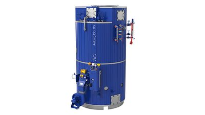
- Aalborg OL (12.5-55 t/h, 9/18 bar)
- Aalborg D (25-120 t/h, 18 bar, Tanker-Design)
- Aalborg OM (8-45 t/h, Mittelkapazität)
- Mission OS (bis 6 t/h, Vertical Auxiliary)
- Area: Tube body leakage due to corrosion, pitting, deposits (scale/sludge) or wearCheck: Internal visual inspection of all steam/water tubes; perform pressure test if suspected; seal leaking tube with conical stop valve after steel wire brush cleaning of tube ends. Leaking tubes must be renewed.
- Area: Water level regulation: failure of differential pressure transmitter or feedwater control valve leads to flooding/drying outCheck: Check DP transmitter unit (external reference/variable leg, 4–20 mA output); feedwater control valve functional test; sight glass for cracks, contamination; test alarm function in control unit
- Area: Safety valve failure or incorrect opening/closing pressures — overpressure or inadequate emergency steam reliefCheck: Test two safety valves under full-load steam: pressure build-up 7 min. max. +6% working pressure permissible (water tubes); pop-point of each valve max. ±3% from set pressure; class notation: perform opening + accumulation test under classifier supervision
- Area: Furnace refractory damage (cracks, spalling) or soot/corrosion → heat leaks, furnace instability, drum overheatingCheck: Inspect furnace walls and refractory lining visually (min. 2x/year); check for cracks, moisture, soot deposits. Check lower tube plate (insulation + form refractory). After 3–4 weeks operation: perform blow-down, inspect/clean boiler, remove sludge
- Area: Loss of pressure integrity due to corrosion, cracks, rivets or welds → leakage, operating loss, safety riskCheck: Hydrostatic test: fill boiler with water 21–65 °C (water tubes max. 71 °C). Pressure: 1.5× MAWP (non-entry) or 1.25× MAWP (entry). Secure safety valves with clamps. Check all seal surfaces, rivets, welds for leaks. Class notation: every 2 years (up to 8 years), then annually
- Area: Internal corrosion (water side), scale deposits or fire side soot/flocking → tube wear, heat loss, contaminationCheck: Class survey: water side (steam drum, water drum, all tubes) check for corrosion/cracks/deposits; fire side (furnace, flue gas path) check for soot/flocking (min. 2x/year). Man holes (top/bottom) permit access. If necessary use ultrasonic/endoscope for deeper defects
Type-universal inspection points for Alfa Laval Aalborg oil-fired marine steam boiler (Water Tube / D-Type) (Aalborg + Class/eCFR, 2026-06). Per-model specs not auto-populated.
- Dual heat source allows continuous steam generation at sea (exhaust gas) and in port (oil firing).
- High steam output range (12.5–120 t/h) covers most auxiliary needs of tankers and bulk carriers.
- Compact D‑type water‑tube construction with membrane walls provides good thermal efficiency and low refractory mass.
- Integrated BOG (boil‑off gas) management for LNG/LPG carriers reduces fuel loss.
- Design pressure options (9 bar or 18 bar) give flexibility for different vessel power systems.
- Complex control system for switching between exhaust‑gas and oil firing requires skilled operators.
- Soot buildup in the economizer tubes demands regular soot‑blowing and thorough water treatment.
- Tube bundle corrosion or pitting can lead to leaks; inspection and hydrostatic testing are intensive.
- Higher capital cost compared with single‑fuel fire‑tube boilers.
- Space requirements for the dual‑source arrangement may be limiting on smaller vessels.
- Dampfkapazität OL
- 12.500–55.000 kg/h (mit BOG-Management)
- Dampfkapazität D
- 25–120 t/h (Tanker-Hauptkessel)
- Designdrücke
- 9 or 18 bar(g)
- Konstruktion
- Zweritrommel (Dampftrommel/Wassertrommel), Membranwände, Generatorröhrenbank
- Rohrsystem
- Gerade Pin-Tubes mit Schwenk-Pins, externe Fallrohre (Aalborg D)
- Brenner-typ
- Oelgefeuert (Standard), Dual-Fuel optional, KBSD/Aalborg-Brenner
- Refraktär
- Minimal im Feuerraum, Isolations- + Formrefraktär an Rohrplatte
- Aalborg OL (12.5-55 t/h, 9/18 bar)
- Aalborg D (25-120 t/h, 18 bar, Tanker-Design)
- Aalborg OM (8-45 t/h, Mittelkapazität)
- Mission OS (bis 6 t/h, Vertical Auxiliary)
- Area: Tube body leakage due to corrosion, pitting, deposits (scale/sludge) or wearCheck: Internal visual inspection of all steam/water tubes; perform pressure test if suspected; seal leaking tube with conical stop valve after steel wire brush cleaning of tube ends. Leaking tubes must be renewed.
- Area: Water level regulation: failure of differential pressure transmitter or feedwater control valve leads to flooding/drying outCheck: Check DP transmitter unit (external reference/variable leg, 4–20 mA output); feedwater control valve functional test; sight glass for cracks, contamination; test alarm function in control unit
- Area: Safety valve failure or incorrect opening/closing pressures — overpressure or inadequate emergency steam reliefCheck: Test two safety valves under full-load steam: pressure build-up 7 min. max. +6% working pressure permissible (water tubes); pop-point of each valve max. ±3% from set pressure; class notation: perform opening + accumulation test under classifier supervision
- Area: Furnace refractory damage (cracks, spalling) or soot/corrosion → heat leaks, furnace instability, drum overheatingCheck: Inspect furnace walls and refractory lining visually (min. 2x/year); check for cracks, moisture, soot deposits. Check lower tube plate (insulation + form refractory). After 3–4 weeks operation: perform blow-down, inspect/clean boiler, remove sludge
- Area: Loss of pressure integrity due to corrosion, cracks, rivets or welds → leakage, operating loss, safety riskCheck: Hydrostatic test: fill boiler with water 21–65 °C (water tubes max. 71 °C). Pressure: 1.5× MAWP (non-entry) or 1.25× MAWP (entry). Secure safety valves with clamps. Check all seal surfaces, rivets, welds for leaks. Class notation: every 2 years (up to 8 years), then annually
- Area: Internal corrosion (water side), scale deposits or fire side soot/flocking → tube wear, heat loss, contaminationCheck: Class survey: water side (steam drum, water drum, all tubes) check for corrosion/cracks/deposits; fire side (furnace, flue gas path) check for soot/flocking (min. 2x/year). Man holes (top/bottom) permit access. If necessary use ultrasonic/endoscope for deeper defects
Type-universal inspection points for Alfa Laval Aalborg oil-fired marine steam boiler (Water Tube / D-Type) (Aalborg + Class/eCFR, 2026-06). Per-model specs not auto-populated.
- Dampfkapazität OL
- 12.500–55.000 kg/h (mit BOG-Management)
- Dampfkapazität D
- 25–120 t/h (Tanker-Hauptkessel)
- Designdrücke
- 9 or 18 bar(g)
- Konstruktion
- Zweritrommel (Dampftrommel/Wassertrommel), Membranwände, Generatorröhrenbank
- Rohrsystem
- Gerade Pin-Tubes mit Schwenk-Pins, externe Fallrohre (Aalborg D)
- Brenner-typ
- Oelgefeuert (Standard), Dual-Fuel optional, KBSD/Aalborg-Brenner
- Refraktär
- Minimal im Feuerraum, Isolations- + Formrefraktär an Rohrplatte
- Aalborg OL (12.5-55 t/h, 9/18 bar)
- Aalborg D (25-120 t/h, 18 bar, Tanker-Design)
- Aalborg OM (8-45 t/h, Mittelkapazität)
- Mission OS (bis 6 t/h, Vertical Auxiliary)
- Area: Tube body leakage due to corrosion, pitting, deposits (scale/sludge) or wearCheck: Internal visual inspection of all steam/water tubes; perform pressure test if suspected; seal leaking tube with conical stop valve after steel wire brush cleaning of tube ends. Leaking tubes must be renewed.
- Area: Water level regulation: failure of differential pressure transmitter or feedwater control valve leads to flooding/drying outCheck: Check DP transmitter unit (external reference/variable leg, 4–20 mA output); feedwater control valve functional test; sight glass for cracks, contamination; test alarm function in control unit
- Area: Safety valve failure or incorrect opening/closing pressures — overpressure or inadequate emergency steam reliefCheck: Test two safety valves under full-load steam: pressure build-up 7 min. max. +6% working pressure permissible (water tubes); pop-point of each valve max. ±3% from set pressure; class notation: perform opening + accumulation test under classifier supervision
- Area: Furnace refractory damage (cracks, spalling) or soot/corrosion → heat leaks, furnace instability, drum overheatingCheck: Inspect furnace walls and refractory lining visually (min. 2x/year); check for cracks, moisture, soot deposits. Check lower tube plate (insulation + form refractory). After 3–4 weeks operation: perform blow-down, inspect/clean boiler, remove sludge
- Area: Loss of pressure integrity due to corrosion, cracks, rivets or welds → leakage, operating loss, safety riskCheck: Hydrostatic test: fill boiler with water 21–65 °C (water tubes max. 71 °C). Pressure: 1.5× MAWP (non-entry) or 1.25× MAWP (entry). Secure safety valves with clamps. Check all seal surfaces, rivets, welds for leaks. Class notation: every 2 years (up to 8 years), then annually
- Area: Internal corrosion (water side), scale deposits or fire side soot/flocking → tube wear, heat loss, contaminationCheck: Class survey: water side (steam drum, water drum, all tubes) check for corrosion/cracks/deposits; fire side (furnace, flue gas path) check for soot/flocking (min. 2x/year). Man holes (top/bottom) permit access. If necessary use ultrasonic/endoscope for deeper defects
Type-universal inspection points for Alfa Laval Aalborg oil-fired marine steam boiler (Water Tube / D-Type) (Aalborg + Class/eCFR, 2026-06). Per-model specs not auto-populated.
- Dampfkapazität OL
- 12.500–55.000 kg/h (mit BOG-Management)
- Dampfkapazität D
- 25–120 t/h (Tanker-Hauptkessel)
- Designdrücke
- 9 or 18 bar(g)
- Konstruktion
- Zweritrommel (Dampftrommel/Wassertrommel), Membranwände, Generatorröhrenbank
- Rohrsystem
- Gerade Pin-Tubes mit Schwenk-Pins, externe Fallrohre (Aalborg D)
- Brenner-typ
- Oelgefeuert (Standard), Dual-Fuel optional, KBSD/Aalborg-Brenner
- Refraktär
- Minimal im Feuerraum, Isolations- + Formrefraktär an Rohrplatte
- Aalborg OL (12.5-55 t/h, 9/18 bar)
- Aalborg D (25-120 t/h, 18 bar, Tanker-Design)
- Aalborg OM (8-45 t/h, Mittelkapazität)
- Mission OS (bis 6 t/h, Vertical Auxiliary)
- Area: Tube body leakage due to corrosion, pitting, deposits (scale/sludge) or wearCheck: Internal visual inspection of all steam/water tubes; perform pressure test if suspected; seal leaking tube with conical stop valve after steel wire brush cleaning of tube ends. Leaking tubes must be renewed.
- Area: Water level regulation: failure of differential pressure transmitter or feedwater control valve leads to flooding/drying outCheck: Check DP transmitter unit (external reference/variable leg, 4–20 mA output); feedwater control valve functional test; sight glass for cracks, contamination; test alarm function in control unit
- Area: Safety valve failure or incorrect opening/closing pressures — overpressure or inadequate emergency steam reliefCheck: Test two safety valves under full-load steam: pressure build-up 7 min. max. +6% working pressure permissible (water tubes); pop-point of each valve max. ±3% from set pressure; class notation: perform opening + accumulation test under classifier supervision
- Area: Furnace refractory damage (cracks, spalling) or soot/corrosion → heat leaks, furnace instability, drum overheatingCheck: Inspect furnace walls and refractory lining visually (min. 2x/year); check for cracks, moisture, soot deposits. Check lower tube plate (insulation + form refractory). After 3–4 weeks operation: perform blow-down, inspect/clean boiler, remove sludge
- Area: Loss of pressure integrity due to corrosion, cracks, rivets or welds → leakage, operating loss, safety riskCheck: Hydrostatic test: fill boiler with water 21–65 °C (water tubes max. 71 °C). Pressure: 1.5× MAWP (non-entry) or 1.25× MAWP (entry). Secure safety valves with clamps. Check all seal surfaces, rivets, welds for leaks. Class notation: every 2 years (up to 8 years), then annually
- Area: Internal corrosion (water side), scale deposits or fire side soot/flocking → tube wear, heat loss, contaminationCheck: Class survey: water side (steam drum, water drum, all tubes) check for corrosion/cracks/deposits; fire side (furnace, flue gas path) check for soot/flocking (min. 2x/year). Man holes (top/bottom) permit access. If necessary use ultrasonic/endoscope for deeper defects
Type-universal inspection points for Alfa Laval Aalborg oil-fired marine steam boiler (Water Tube / D-Type) (Aalborg + Class/eCFR, 2026-06). Per-model specs not auto-populated.
- Dampfkapazität OL
- 12.500–55.000 kg/h (mit BOG-Management)
- Dampfkapazität D
- 25–120 t/h (Tanker-Hauptkessel)
- Designdrücke
- 9 or 18 bar(g)
- Konstruktion
- Zweritrommel (Dampftrommel/Wassertrommel), Membranwände, Generatorröhrenbank
- Rohrsystem
- Gerade Pin-Tubes mit Schwenk-Pins, externe Fallrohre (Aalborg D)
- Brenner-typ
- Oelgefeuert (Standard), Dual-Fuel optional, KBSD/Aalborg-Brenner
- Refraktär
- Minimal im Feuerraum, Isolations- + Formrefraktär an Rohrplatte
- Aalborg OL (12.5-55 t/h, 9/18 bar)
- Aalborg D (25-120 t/h, 18 bar, Tanker-Design)
- Aalborg OM (8-45 t/h, Mittelkapazität)
- Mission OS (bis 6 t/h, Vertical Auxiliary)
- Area: Tube body leakage due to corrosion, pitting, deposits (scale/sludge) or wearCheck: Internal visual inspection of all steam/water tubes; perform pressure test if suspected; seal leaking tube with conical stop valve after steel wire brush cleaning of tube ends. Leaking tubes must be renewed.
- Area: Water level regulation: failure of differential pressure transmitter or feedwater control valve leads to flooding/drying outCheck: Check DP transmitter unit (external reference/variable leg, 4–20 mA output); feedwater control valve functional test; sight glass for cracks, contamination; test alarm function in control unit
- Area: Safety valve failure or incorrect opening/closing pressures — overpressure or inadequate emergency steam reliefCheck: Test two safety valves under full-load steam: pressure build-up 7 min. max. +6% working pressure permissible (water tubes); pop-point of each valve max. ±3% from set pressure; class notation: perform opening + accumulation test under classifier supervision
- Area: Furnace refractory damage (cracks, spalling) or soot/corrosion → heat leaks, furnace instability, drum overheatingCheck: Inspect furnace walls and refractory lining visually (min. 2x/year); check for cracks, moisture, soot deposits. Check lower tube plate (insulation + form refractory). After 3–4 weeks operation: perform blow-down, inspect/clean boiler, remove sludge
- Area: Loss of pressure integrity due to corrosion, cracks, rivets or welds → leakage, operating loss, safety riskCheck: Hydrostatic test: fill boiler with water 21–65 °C (water tubes max. 71 °C). Pressure: 1.5× MAWP (non-entry) or 1.25× MAWP (entry). Secure safety valves with clamps. Check all seal surfaces, rivets, welds for leaks. Class notation: every 2 years (up to 8 years), then annually
- Area: Internal corrosion (water side), scale deposits or fire side soot/flocking → tube wear, heat loss, contaminationCheck: Class survey: water side (steam drum, water drum, all tubes) check for corrosion/cracks/deposits; fire side (furnace, flue gas path) check for soot/flocking (min. 2x/year). Man holes (top/bottom) permit access. If necessary use ultrasonic/endoscope for deeper defects
Type-universal inspection points for Alfa Laval Aalborg oil-fired marine steam boiler (Water Tube / D-Type) (Aalborg + Class/eCFR, 2026-06). Per-model specs not auto-populated.
- Dampfkapazität OL
- 12.500–55.000 kg/h (mit BOG-Management)
- Dampfkapazität D
- 25–120 t/h (Tanker-Hauptkessel)
- Designdrücke
- 9 or 18 bar(g)
- Konstruktion
- Zweritrommel (Dampftrommel/Wassertrommel), Membranwände, Generatorröhrenbank
- Rohrsystem
- Gerade Pin-Tubes mit Schwenk-Pins, externe Fallrohre (Aalborg D)
- Brenner-typ
- Oelgefeuert (Standard), Dual-Fuel optional, KBSD/Aalborg-Brenner
- Refraktär
- Minimal im Feuerraum, Isolations- + Formrefraktär an Rohrplatte
- Aalborg OL (12.5-55 t/h, 9/18 bar)
- Aalborg D (25-120 t/h, 18 bar, Tanker-Design)
- Aalborg OM (8-45 t/h, Mittelkapazität)
- Mission OS (bis 6 t/h, Vertical Auxiliary)
- Area: Tube body leakage due to corrosion, pitting, deposits (scale/sludge) or wearCheck: Internal visual inspection of all steam/water tubes; perform pressure test if suspected; seal leaking tube with conical stop valve after steel wire brush cleaning of tube ends. Leaking tubes must be renewed.
- Area: Water level regulation: failure of differential pressure transmitter or feedwater control valve leads to flooding/drying outCheck: Check DP transmitter unit (external reference/variable leg, 4–20 mA output); feedwater control valve functional test; sight glass for cracks, contamination; test alarm function in control unit
- Area: Safety valve failure or incorrect opening/closing pressures — overpressure or inadequate emergency steam reliefCheck: Test two safety valves under full-load steam: pressure build-up 7 min. max. +6% working pressure permissible (water tubes); pop-point of each valve max. ±3% from set pressure; class notation: perform opening + accumulation test under classifier supervision
- Area: Furnace refractory damage (cracks, spalling) or soot/corrosion → heat leaks, furnace instability, drum overheatingCheck: Inspect furnace walls and refractory lining visually (min. 2x/year); check for cracks, moisture, soot deposits. Check lower tube plate (insulation + form refractory). After 3–4 weeks operation: perform blow-down, inspect/clean boiler, remove sludge
- Area: Loss of pressure integrity due to corrosion, cracks, rivets or welds → leakage, operating loss, safety riskCheck: Hydrostatic test: fill boiler with water 21–65 °C (water tubes max. 71 °C). Pressure: 1.5× MAWP (non-entry) or 1.25× MAWP (entry). Secure safety valves with clamps. Check all seal surfaces, rivets, welds for leaks. Class notation: every 2 years (up to 8 years), then annually
- Area: Internal corrosion (water side), scale deposits or fire side soot/flocking → tube wear, heat loss, contaminationCheck: Class survey: water side (steam drum, water drum, all tubes) check for corrosion/cracks/deposits; fire side (furnace, flue gas path) check for soot/flocking (min. 2x/year). Man holes (top/bottom) permit access. If necessary use ultrasonic/endoscope for deeper defects
Type-universal inspection points for Alfa Laval Aalborg oil-fired marine steam boiler (Water Tube / D-Type) (Aalborg + Class/eCFR, 2026-06). Per-model specs not auto-populated.

- Dampfkapazität OL
- 12.500–55.000 kg/h (mit BOG-Management)
- Dampfkapazität D
- 25–120 t/h (Tanker-Hauptkessel)
- Designdrücke
- 9 or 18 bar(g)
- Konstruktion
- Zweritrommel (Dampftrommel/Wassertrommel), Membranwände, Generatorröhrenbank
- Rohrsystem
- Gerade Pin-Tubes mit Schwenk-Pins, externe Fallrohre (Aalborg D)
- Brenner-typ
- Oelgefeuert (Standard), Dual-Fuel optional, KBSD/Aalborg-Brenner
- Refraktär
- Minimal im Feuerraum, Isolations- + Formrefraktär an Rohrplatte
- Aalborg OL (12.5-55 t/h, 9/18 bar)
- Aalborg D (25-120 t/h, 18 bar, Tanker-Design)
- Aalborg OM (8-45 t/h, Mittelkapazität)
- Mission OS (bis 6 t/h, Vertical Auxiliary)
- Area: Tube body leakage due to corrosion, pitting, deposits (scale/sludge) or wearCheck: Internal visual inspection of all steam/water tubes; perform pressure test if suspected; seal leaking tube with conical stop valve after steel wire brush cleaning of tube ends. Leaking tubes must be renewed.
- Area: Water level regulation: failure of differential pressure transmitter or feedwater control valve leads to flooding/drying outCheck: Check DP transmitter unit (external reference/variable leg, 4–20 mA output); feedwater control valve functional test; sight glass for cracks, contamination; test alarm function in control unit
- Area: Safety valve failure or incorrect opening/closing pressures — overpressure or inadequate emergency steam reliefCheck: Test two safety valves under full-load steam: pressure build-up 7 min. max. +6% working pressure permissible (water tubes); pop-point of each valve max. ±3% from set pressure; class notation: perform opening + accumulation test under classifier supervision
- Area: Furnace refractory damage (cracks, spalling) or soot/corrosion → heat leaks, furnace instability, drum overheatingCheck: Inspect furnace walls and refractory lining visually (min. 2x/year); check for cracks, moisture, soot deposits. Check lower tube plate (insulation + form refractory). After 3–4 weeks operation: perform blow-down, inspect/clean boiler, remove sludge
- Area: Loss of pressure integrity due to corrosion, cracks, rivets or welds → leakage, operating loss, safety riskCheck: Hydrostatic test: fill boiler with water 21–65 °C (water tubes max. 71 °C). Pressure: 1.5× MAWP (non-entry) or 1.25× MAWP (entry). Secure safety valves with clamps. Check all seal surfaces, rivets, welds for leaks. Class notation: every 2 years (up to 8 years), then annually
- Area: Internal corrosion (water side), scale deposits or fire side soot/flocking → tube wear, heat loss, contaminationCheck: Class survey: water side (steam drum, water drum, all tubes) check for corrosion/cracks/deposits; fire side (furnace, flue gas path) check for soot/flocking (min. 2x/year). Man holes (top/bottom) permit access. If necessary use ultrasonic/endoscope for deeper defects
Type-universal inspection points for Alfa Laval Aalborg oil-fired marine steam boiler (Water Tube / D-Type) (Aalborg + Class/eCFR, 2026-06). Per-model specs not auto-populated.
- Dampfkapazität OL
- 12.500–55.000 kg/h (mit BOG-Management)
- Dampfkapazität D
- 25–120 t/h (Tanker-Hauptkessel)
- Designdrücke
- 9 or 18 bar(g)
- Konstruktion
- Zweritrommel (Dampftrommel/Wassertrommel), Membranwände, Generatorröhrenbank
- Rohrsystem
- Gerade Pin-Tubes mit Schwenk-Pins, externe Fallrohre (Aalborg D)
- Brenner-typ
- Oelgefeuert (Standard), Dual-Fuel optional, KBSD/Aalborg-Brenner
- Refraktär
- Minimal im Feuerraum, Isolations- + Formrefraktär an Rohrplatte
- Aalborg OL (12.5-55 t/h, 9/18 bar)
- Aalborg D (25-120 t/h, 18 bar, Tanker-Design)
- Aalborg OM (8-45 t/h, Mittelkapazität)
- Mission OS (bis 6 t/h, Vertical Auxiliary)
- Area: Tube body leakage due to corrosion, pitting, deposits (scale/sludge) or wearCheck: Internal visual inspection of all steam/water tubes; perform pressure test if suspected; seal leaking tube with conical stop valve after steel wire brush cleaning of tube ends. Leaking tubes must be renewed.
- Area: Water level regulation: failure of differential pressure transmitter or feedwater control valve leads to flooding/drying outCheck: Check DP transmitter unit (external reference/variable leg, 4–20 mA output); feedwater control valve functional test; sight glass for cracks, contamination; test alarm function in control unit
- Area: Safety valve failure or incorrect opening/closing pressures — overpressure or inadequate emergency steam reliefCheck: Test two safety valves under full-load steam: pressure build-up 7 min. max. +6% working pressure permissible (water tubes); pop-point of each valve max. ±3% from set pressure; class notation: perform opening + accumulation test under classifier supervision
- Area: Furnace refractory damage (cracks, spalling) or soot/corrosion → heat leaks, furnace instability, drum overheatingCheck: Inspect furnace walls and refractory lining visually (min. 2x/year); check for cracks, moisture, soot deposits. Check lower tube plate (insulation + form refractory). After 3–4 weeks operation: perform blow-down, inspect/clean boiler, remove sludge
- Area: Loss of pressure integrity due to corrosion, cracks, rivets or welds → leakage, operating loss, safety riskCheck: Hydrostatic test: fill boiler with water 21–65 °C (water tubes max. 71 °C). Pressure: 1.5× MAWP (non-entry) or 1.25× MAWP (entry). Secure safety valves with clamps. Check all seal surfaces, rivets, welds for leaks. Class notation: every 2 years (up to 8 years), then annually
- Area: Internal corrosion (water side), scale deposits or fire side soot/flocking → tube wear, heat loss, contaminationCheck: Class survey: water side (steam drum, water drum, all tubes) check for corrosion/cracks/deposits; fire side (furnace, flue gas path) check for soot/flocking (min. 2x/year). Man holes (top/bottom) permit access. If necessary use ultrasonic/endoscope for deeper defects
Type-universal inspection points for Alfa Laval Aalborg oil-fired marine steam boiler (Water Tube / D-Type) (Aalborg + Class/eCFR, 2026-06). Per-model specs not auto-populated.
- Dampfkapazität OL
- 12.500–55.000 kg/h (mit BOG-Management)
- Dampfkapazität D
- 25–120 t/h (Tanker-Hauptkessel)
- Designdrücke
- 9 or 18 bar(g)
- Konstruktion
- Zweritrommel (Dampftrommel/Wassertrommel), Membranwände, Generatorröhrenbank
- Rohrsystem
- Gerade Pin-Tubes mit Schwenk-Pins, externe Fallrohre (Aalborg D)
- Brenner-typ
- Oelgefeuert (Standard), Dual-Fuel optional, KBSD/Aalborg-Brenner
- Refraktär
- Minimal im Feuerraum, Isolations- + Formrefraktär an Rohrplatte
- Aalborg OL (12.5-55 t/h, 9/18 bar)
- Aalborg D (25-120 t/h, 18 bar, Tanker-Design)
- Aalborg OM (8-45 t/h, Mittelkapazität)
- Mission OS (bis 6 t/h, Vertical Auxiliary)
- Area: Tube body leakage due to corrosion, pitting, deposits (scale/sludge) or wearCheck: Internal visual inspection of all steam/water tubes; perform pressure test if suspected; seal leaking tube with conical stop valve after steel wire brush cleaning of tube ends. Leaking tubes must be renewed.
- Area: Water level regulation: failure of differential pressure transmitter or feedwater control valve leads to flooding/drying outCheck: Check DP transmitter unit (external reference/variable leg, 4–20 mA output); feedwater control valve functional test; sight glass for cracks, contamination; test alarm function in control unit
- Area: Safety valve failure or incorrect opening/closing pressures — overpressure or inadequate emergency steam reliefCheck: Test two safety valves under full-load steam: pressure build-up 7 min. max. +6% working pressure permissible (water tubes); pop-point of each valve max. ±3% from set pressure; class notation: perform opening + accumulation test under classifier supervision
- Area: Furnace refractory damage (cracks, spalling) or soot/corrosion → heat leaks, furnace instability, drum overheatingCheck: Inspect furnace walls and refractory lining visually (min. 2x/year); check for cracks, moisture, soot deposits. Check lower tube plate (insulation + form refractory). After 3–4 weeks operation: perform blow-down, inspect/clean boiler, remove sludge
- Area: Loss of pressure integrity due to corrosion, cracks, rivets or welds → leakage, operating loss, safety riskCheck: Hydrostatic test: fill boiler with water 21–65 °C (water tubes max. 71 °C). Pressure: 1.5× MAWP (non-entry) or 1.25× MAWP (entry). Secure safety valves with clamps. Check all seal surfaces, rivets, welds for leaks. Class notation: every 2 years (up to 8 years), then annually
- Area: Internal corrosion (water side), scale deposits or fire side soot/flocking → tube wear, heat loss, contaminationCheck: Class survey: water side (steam drum, water drum, all tubes) check for corrosion/cracks/deposits; fire side (furnace, flue gas path) check for soot/flocking (min. 2x/year). Man holes (top/bottom) permit access. If necessary use ultrasonic/endoscope for deeper defects
Type-universal inspection points for Alfa Laval Aalborg oil-fired marine steam boiler (Water Tube / D-Type) (Aalborg + Class/eCFR, 2026-06). Per-model specs not auto-populated.
Kangrim
6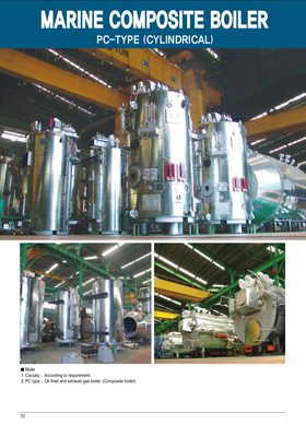
- Soot fire risk
- Fin tube erosion
- Bypass damper malfunction
- High thermal recovery efficiency compared with conventional seawater‑cooled boilers
- Compact footprint suitable for vessels with limited space
- Direct integration with existing steam generation systems
- Reduces fuel consumption by offsetting auxiliary boiler load
- Soot fire risk if exhaust gas temperature differential is not closely monitored
- Fin‑tube erosion in high‑velocity or high‑sulphur exhaust streams
- Bypass damper can malfunction, leading to pressure and flow instability
- Requires routine soot‑blowing each watch, increasing crew workload
- Soot accumulation and fire risk
- Tube erosion
- Casing cracking from thermal stress
- High heat recovery efficiency, delivering measurable fuel savings
- Compact finned‑tube design reduces installation footprint
- Proven on HHI, DSME and SHI newbuilds, giving a solid service record
- Compatible with low‑sulfur fuels and exhaust gas cleaning systems
- Modular casing allows relatively easy inspection and tube replacement
- Soot buildup risk; requires strict fire‑prevention procedures similar to Aalborg units
- Tube erosion accelerated by high sulfur or particulate content in exhaust gases
- Casing can develop thermal‑stress cracks if temperature gradients are not well managed
- Maintenance intensive: annual tube thickness measurements and periodic cleaning required
- Less tolerant of wide exhaust gas temperature swings compared with some HRSG designs
- Heat-source or burner failure caused by fuel, ignition, exhaust-flow or control faults, noticed as failed start, trip or reduced heat production
- Low or unstable water/fluid circulation caused by pump, level-control or valve faults, noticed as alarms, local overheating or loss of output
- Heating-surface fouling caused by soot, scale or deposits, noticed as reduced efficiency, higher exhaust temperature or increased pressure drop
- Tube, coil or pressure-part leakage caused by corrosion, erosion, scale or thermal stress, noticed as water/fluid loss, steam leakage or contamination of the gas side
- Safety/control instrumentation failure caused by sensor, valve, actuator or interlock faults, noticed as unstable operation, nuisance trips or failed functional tests
- Heat-source or burner failure caused by fuel, ignition, exhaust-flow or control faults, noticed as failed start, trip or reduced heat production
- Low or unstable water/fluid circulation caused by pump, level-control or valve faults, noticed as alarms, local overheating or loss of output
- Heating-surface fouling caused by soot, scale or deposits, noticed as reduced efficiency, higher exhaust temperature or increased pressure drop
- Tube, coil or pressure-part leakage caused by corrosion, erosion, scale or thermal stress, noticed as water/fluid loss, steam leakage or contamination of the gas side
- Safety/control instrumentation failure caused by sensor, valve, actuator or interlock faults, noticed as unstable operation, nuisance trips or failed functional tests
- Heat-source or burner failure caused by fuel, ignition, exhaust-flow or control faults, noticed as failed start, trip or reduced heat production
- Low or unstable water/fluid circulation caused by pump, level-control or valve faults, noticed as alarms, local overheating or loss of output
- Heating-surface fouling caused by soot, scale or deposits, noticed as reduced efficiency, higher exhaust temperature or increased pressure drop
- Tube, coil or pressure-part leakage caused by corrosion, erosion, scale or thermal stress, noticed as water/fluid loss, steam leakage or contamination of the gas side
- Safety/control instrumentation failure caused by sensor, valve, actuator or interlock faults, noticed as unstable operation, nuisance trips or failed functional tests
- Heat-source or burner failure caused by fuel, ignition, exhaust-flow or control faults, noticed as failed start, trip or reduced heat production
- Low or unstable water/fluid circulation caused by pump, level-control or valve faults, noticed as alarms, local overheating or loss of output
- Heating-surface fouling caused by soot, scale or deposits, noticed as reduced efficiency, higher exhaust temperature or increased pressure drop
- Tube, coil or pressure-part leakage caused by corrosion, erosion, scale or thermal stress, noticed as water/fluid loss, steam leakage or contamination of the gas side
- Safety/control instrumentation failure caused by sensor, valve, actuator or interlock faults, noticed as unstable operation, nuisance trips or failed functional tests
Aalborg
1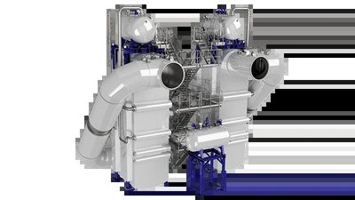
- Soot fire (most dangerous!)
- Tube leakage from corrosion
- Soot accumulation
- Water hammer
- High thermal efficiency (≈80% of exhaust heat recovered)
- Compact footprint suitable for space‑constrained vessels
- Integrated automatic soot‑blowing reduces fire risk when maintained properly
- Robust steel tube construction tolerates high soot loads
- Compatible with medium‑speed diesel engines across a wide power range
- Requires strict water‑level monitoring; low level can cause overheating
- Soot accumulation can lead to fires if blow schedule is missed
- Tube corrosion possible in acidic condensate environments, demanding regular inspection
- Water hammer incidents reported if sudden flow changes occur
- Higher capital cost compared with simple economizers lacking soot‑blow systems
Usui
1
- Soot fire
- Tube fin damage
- Condensation corrosion at low load
- High heat recovery efficiency (up to ~90% of available exhaust heat)
- Compact footprint suitable for retrofits on existing vessels
- Robust Japanese manufacturing quality with proven long‑term reliability at steady loads
- Quick start‑up and integration with low‑speed diesel engine exhaust systems
- Susceptible to condensation corrosion when operated at prolonged low loads
- Risk of soot fire if exhaust filtration is inadequate
- Tube fin damage can occur under fluctuating load conditions, requiring regular inspection
- Maintenance intensity increases with frequent start‑stop cycles