Rate of Turn Indicator
A rate of turn indicator does not tell the bridge which way the ship is pointing, only how fast that heading is changing -- a distinction that matters most in the middle of a turn, exactly when the heading display alone is hardest to read accurately.
Read more — Rate of Turn Indicator explained ▾
What Makes a Rate of Turn Indicator Different
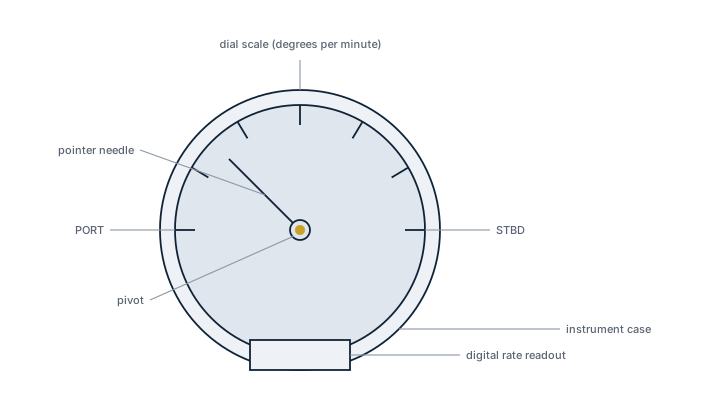
A gyrocompass or heading sensor reports where the bow is pointing at any instant. A rate of turn indicator (ROTI) reports the rate of change of that heading, typically in degrees per minute, a different and complementary piece of information. During a turn in a narrow channel or a collision-avoidance manoeuvre, watching the rate of turn is often more useful than watching the heading number itself, because it shows immediately whether the rudder action is producing the turn rate intended and whether the turn needs to be checked before overshooting. Some vessels combine rate of turn with a maximum-turn-rate alarm to warn against excessive heel or a manoeuvre beyond the vessel's stability limits.
Main Components
Rate Sensor
Most modern ROTIs derive rate of turn directly from the ship's gyrocompass or inertial heading sensor by differentiating the heading signal electronically, rather than using a separate mechanical sensor; some standalone units use their own rate gyro.
Display
A dial or digital display calibrated in degrees per minute, commonly with a range around plus or minus 30 to 90 degrees per minute, mounted where it is visible to the officer of the watch during manoeuvring, typically alongside or integrated into the conning display.
Alarm Function
Where fitted, a settable high-rate alarm alerts the bridge team if the turn rate exceeds a preset threshold, useful as a check against an unintended excessive turn from an autopilot fault or steering gear issue.
Data Output
On integrated bridge systems the rate of turn signal feeds the electronic chart display and radar/ARPA for predicted vector display and is logged by the voyage data recorder.
Selection and Sizing
Selection is less about a numerical sizing calculation than about integration: the ROTI must be compatible with the ship's existing heading source, gyrocompass or satellite compass, and data bus, commonly NMEA 0183 or 2000 on smaller vessels, or a proprietary bridge system bus on larger integrated bridges, and its display range and update rate must suit the vessel's manoeuvring characteristics -- a fast ferry with rapid heading changes needs a higher update rate than a slow-turning bulk carrier.
| Parameter | Typical Value |
|---|---|
| Display units | Degrees per minute |
| Typical display range | +/-30 to +/-90 deg/min |
| Data interface | NMEA 0183/2000 or bridge system bus |
Regulations and Class
SOLAS Chapter V requires a rate of turn indicator on vessels of 50,000 gross tonnage and above, and it is a common fit on smaller vessels even where not mandated, because of its value during pilotage and manoeuvring. Where fitted, it must meet IMO performance standards for shipborne rate of turn indicators and carry type approval consistent with the vessel's other navigation equipment; class societies check its integration and correct function as part of the navigation equipment survey.
Typical Faults
| Fault | Cause | Consequence |
|---|---|---|
| Erratic or jumping reading | Noisy or degraded heading sensor signal feeding the rate calculation | Unreliable manoeuvring information during pilotage |
| Frozen display | Data bus interface fault or loss of heading source signal | Officer of the watch loses turn-rate reference, must rely on heading alone |
| False high-rate alarms | Alarm threshold set too low for the vessel's normal manoeuvring rates | Alarm fatigue, crew starts ignoring the alarm |
| Mismatch with radar predicted vector | Configuration error in the data feed to the ARPA | Confusing or contradictory manoeuvring display during collision avoidance |
What to Look for in a Supplier
- Confirmed compatibility with the vessel's existing heading sensor and bridge data bus before ordering, since a mismatched interface is the most common integration failure.
- Type approval consistent with the vessel's other navigation equipment and flag state requirements.
- Display readability at the actual mounting position, including in direct sunlight if bridge-wing visible.
- Support for firmware or configuration updates if the unit integrates into a wider bridge system.
Cross-check the rate of turn reading against a stopwatch and the compass repeater during a full swing at sea trial or annual test -- a ROTI that is quietly a few degrees per minute off is far more dangerous than one that has failed outright, because nobody notices until a tight manoeuvre goes wrong.
Typical Manufacturers
12 manufacturers · 13 models
Tokyo Keiki
2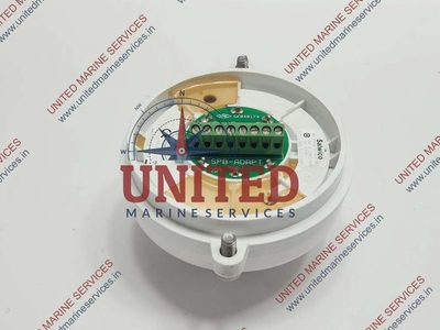
- Sensor, antenna or transducer fouling, damage or misalignment causes unstable, missing or inaccurate data
- Power-supply or processor faults cause resets, blank displays or complete loss of indication
- Cable, connector or network faults cause intermittent data or loss of outputs to dependent bridge systems
- Incorrect configuration or calibration causes persistent disagreement with independent references
- Display, storage or software faults cause frozen values, alarms or unavailable navigation functions
- IMO approved, meeting mandatory performance standards
- Compact Japanese design known for mechanical reliability
- Clear analog/digital display within a ±30°/min range
- Simple wiring interface compatible with most legacy bridge consoles
- Sensor calibration can drift and requires periodic verification
- Display brightness may dim under low‑light conditions
- Limited integration options; newer NMEA 2000 or Ethernet interfaces are not standard
- Turn‑rate range capped at ±30°/min, unsuitable for high‑maneuverability craft
- Loss of electrical, hydraulic, pneumatic, or other service supply caused by a tripped protection device, leakage, blockage, or upstream fault results in failed starting or loss of function
- Mechanical wear, corrosion, fouling, or contamination of moving and wetted parts causes increased noise, leakage, sticking, vibration, or reduced performance
- Seal, gasket, hose, cable, or connection deterioration from age, heat, vibration, or environmental exposure produces visible leakage, intermittent signals, or loss of pressure
- Sensor, switch, actuator, relay, or control-system faults can cause incorrect indication, nuisance alarms, failed automatic sequences, or loss of remote control
- Incorrect adjustment, assembly, or maintenance can lead to unstable operation, recurrent alarms, or performance that differs from the vessel's normal baseline
Consilium Marine & Safety
1
- Component wear due to operating hours and environmental conditions
- Corrosion due to seawater/salt air exposure
- Electronics/control failure due to moisture or vibration
- Service interval overrun causes premature failure
- Customizable temperature class allows tailoring to specific spaces
- High IP rating (e.g., IP66) protects against dust and water ingress in harsh marine environments
- Designed for integration with existing ship alarm and monitoring systems
- Meets major classification society requirements for fire detection equipment
- Detects only temperature rise – no smoke or flame sensing capability
- Susceptible to corrosion if maintenance intervals are missed, especially in salt‑air exposure
- Requires regular calibration and functional testing per manufacturer handbook
- Initial procurement cost can be higher than basic heat sensors
Dansk Wilton
1
- Component wear due to operating hours and environmental conditions
- Corrosion due to seawater/salt air exposure
- Electronics/control failure due to moisture or vibration
- Service interval overrun causes premature failure
- Proven DNV‑approved design for class‑society compliance
- Wide selection of DW Contract media (1100–1900 g/m²) allowing flexible recording length and durability
- Robust mechanical construction tolerant to harsh marine environments when maintained per manual
- Simple, intuitive readout directly on the bridge wheel – no complex software required
- Spare‑part support from manufacturer and clear maintenance intervals
- Mechanical parts subject to wear; requires regular inspection and possible part replacement
- Sensitive to moisture and vibration – excessive exposure can cause recording errors or electronic failure
- Analog output limits integration with modern digital bridge systems without additional converters
- Paper roll adds weight and occupies space compared with fully electronic indicators
- Calibration must be performed periodically, adding to maintenance workload
DESMI
1
- Component wear due to operating hours and environmental conditions
- Corrosion due to seawater/salt air exposure
- Electronics/control failure due to moisture or vibration
- Service interval overrun causes premature failure
- Compact footprint suitable for vessels with limited space
- Modular design allows easy scaling within the 35–1,740 m³/h range
- No chemical additives required – lower environmental impact and operating cost
- Integrated monitoring and control system simplifies compliance reporting
- Proven IMO D‑2 type approval and USCG acceptance
- Performance can be reduced in highly turbid or fouling water without adequate pre‑filtration
- UV lamps require regular cleaning/replacement – higher maintenance discipline
- Maximum flow rating (1,740 m³/h) may be insufficient for very large tankers or bulk carriers
- Initial capital cost is higher than simple chemical dosing systems
- Sensitive to vibration and moisture; requires careful installation
Furuno
1
- Loss of electrical, hydraulic, pneumatic, or other service supply caused by a tripped protection device, leakage, blockage, or upstream fault results in failed starting or loss of function
- Mechanical wear, corrosion, fouling, or contamination of moving and wetted parts causes increased noise, leakage, sticking, vibration, or reduced performance
- Seal, gasket, hose, cable, or connection deterioration from age, heat, vibration, or environmental exposure produces visible leakage, intermittent signals, or loss of pressure
- Sensor, switch, actuator, relay, or control-system faults can cause incorrect indication, nuisance alarms, failed automatic sequences, or loss of remote control
- Incorrect adjustment, assembly, or maintenance can lead to unstable operation, recurrent alarms, or performance that differs from the vessel's normal baseline
JRC
1
- Loss of electrical, hydraulic, pneumatic, or other service supply caused by a tripped protection device, leakage, blockage, or upstream fault results in failed starting or loss of function
- Mechanical wear, corrosion, fouling, or contamination of moving and wetted parts causes increased noise, leakage, sticking, vibration, or reduced performance
- Seal, gasket, hose, cable, or connection deterioration from age, heat, vibration, or environmental exposure produces visible leakage, intermittent signals, or loss of pressure
- Sensor, switch, actuator, relay, or control-system faults can cause incorrect indication, nuisance alarms, failed automatic sequences, or loss of remote control
- Incorrect adjustment, assembly, or maintenance can lead to unstable operation, recurrent alarms, or performance that differs from the vessel's normal baseline
Kongsberg Maritime
1
- Component wear due to operating hours and environmental conditions
- Corrosion due to seawater/salt air exposure
- Electronics/control failure due to moisture or vibration
- Service interval overrun causes premature failure
- Seamless integration with other Kongsberg Bridge sensors and displays, enabling a unified user interface
- High reliability and low mechanical wear compared with traditional gyro or pendulum ROT devices
- Digital output compatible with NMEA 0183/2000 standards for easy data sharing across ship systems
- Meets IMO SOLAS requirements for rate‑of‑turn indication without additional calibration hardware
- Modular design simplifies installation and replacement during scheduled dry‑dock periods
- Higher upfront cost than basic mechanical ROT indicators
- Requires a functional Kongsberg data network and power supply; loss of power or bus failure disables the display
- Limited interoperability with non‑Kongsberg bridge consoles, potentially requiring additional interface modules
- Sensitive to severe vibration or moisture ingress if not installed according to manufacturer guidelines
- Software updates must be managed through Kongsberg’s support portal, adding a maintenance planning step
Raytheon Anschuetz
1
- Sensor, antenna or transducer damage causes unstable, missing or inaccurate navigation data
- Power-supply failure causes receiver or display reset and complete loss of output
- Cable, connector or interface faults cause intermittent data or loss of signals to dependent systems
- Incorrect alignment, calibration or configuration causes persistent disagreement with independent references
- Processor or display faults cause frozen values, alarms or unavailable navigation information
Raytheon Anschütz
1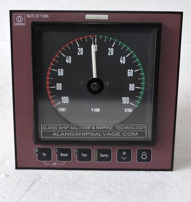
- Sensor, antenna or transducer fouling, damage or misalignment causes unstable, missing or inaccurate data
- Power-supply or processor faults cause resets, blank displays or complete loss of indication
- Cable, connector or network faults cause intermittent data or loss of outputs to dependent bridge systems
- Incorrect configuration or calibration causes persistent disagreement with independent references
- Display, storage or software faults cause frozen values, alarms or unavailable navigation functions
- Integrated with Synapsis bridge suite for seamless data exchange
- IMO approved, meeting SOLAS performance requirements
- High resolution within ±30°/min range and fast response
- Standalone option simplifies retrofits on older vessels
- Solid‑state gyro reduces mechanical wear
- Gyro sensor can drift, requiring periodic recalibration
- Display calibration may shift over time, affecting accuracy
- Interface compatibility issues with non‑Anschütz bridge systems
- Higher upfront cost compared to basic analog ROT indicators
- Requires proprietary software updates for firmware
Simrad
1
- Loss of electrical, hydraulic, pneumatic, or other service supply caused by a tripped protection device, leakage, blockage, or upstream fault results in failed starting or loss of function
- Mechanical wear, corrosion, fouling, or contamination of moving and wetted parts causes increased noise, leakage, sticking, vibration, or reduced performance
- Seal, gasket, hose, cable, or connection deterioration from age, heat, vibration, or environmental exposure produces visible leakage, intermittent signals, or loss of pressure
- Sensor, switch, actuator, relay, or control-system faults can cause incorrect indication, nuisance alarms, failed automatic sequences, or loss of remote control
- Incorrect adjustment, assembly, or maintenance can lead to unstable operation, recurrent alarms, or performance that differs from the vessel's normal baseline
Sperry Marine
1
- Sensor, antenna or transducer fouling, damage or misalignment causes unstable, missing or inaccurate data
- Power-supply or processor faults cause resets, blank displays or complete loss of indication
- Cable, connector or network faults cause intermittent data or loss of outputs to dependent bridge systems
- Incorrect configuration or calibration causes persistent disagreement with independent references
- Display, storage or software faults cause frozen values, alarms or unavailable navigation functions
- IMO approved and fully compatible with the VisionMaster navigation suite
- Wide measurement range of ±30°/min suitable for most commercial vessels
- Compact electronic design with a clear digital display for quick situational awareness
- Simple integration with existing bridge consoles and autopilot systems
- Sensor performance can degrade over time (aging) requiring periodic recalibration or replacement
- Display backlight may dim or fail, affecting readability in low‑light conditions
- Vibration from mounting points can affect accuracy if not properly isolated
Yokogawa
1
- Sensor, antenna or transducer fouling, damage or misalignment causes unstable, missing or inaccurate data
- Power-supply or processor faults cause resets, blank displays or complete loss of indication
- Cable, connector or network faults cause intermittent data or loss of outputs to dependent bridge systems
- Incorrect configuration or calibration causes persistent disagreement with independent references
- Display, storage or software faults cause frozen values, alarms or unavailable navigation functions
- Compact design fits standard bridge consoles
- Direct integration with other Yokogawa bridge systems
- Proven reliability in long‑service marine environments
- Simple analog/digital display for quick crew interpretation
- Spare parts are limited and only available through third parties
- Sensor drift can develop over time, requiring periodic recalibration
- Display technology may become obsolete compared with newer digital units
- Limited advanced networking features versus modern integrated bridge suites