Speed Log (Correlation)
A correlation speed log measures speed over ground by comparing the seabed acoustic pattern seen by two hull transducers a fixed distance apart, giving useful readings in shallow water where a single Doppler beam would lose bottom lock.
Read more — Speed Log (Correlation) explained ▾
What makes this type
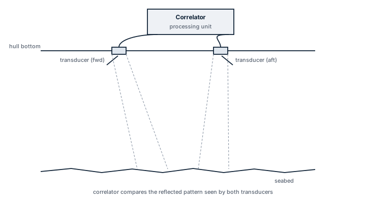
A correlation log finds speed by comparing two snapshots of the seabed acoustic reflection taken by two transducers separated along the ship's fore-and-aft line. As the vessel moves, the reflection pattern seen by the aft transducer at one moment reappears under the forward transducer a short time later; measuring that time delay against the known transducer spacing gives speed over ground directly, without relying on a frequency shift. This sets it apart from the Doppler log family, which measures the frequency shift in the return signal instead, and correlates it against water rather than a fixed distance.
Main components
Transducer pair
Two hull-mounted transducers, fore and aft, with a precisely known separation used as the reference baseline for the delay calculation.
Correlator processing unit
Performs the cross-correlation between the two received signals to extract the time lag, then converts it into speed using the transducer spacing.
Signal conditioning electronics
Filters and amplifies the weak seabed return before correlation, since the reflected signal is far weaker than the outgoing pulse.
Interface and display unit
Outputs speed over ground to the bridge display and feeds NMEA data to radar, ECDIS and the voyage data recorder.
Selection / sizing
- Maximum operating depth: correlation logs need a bottom return within a defined depth range, beyond which they fall back to water-track mode or lose lock entirely.
- Transducer separation, fixed by the hull design, which sets the resolution and update rate of the speed reading.
- Hull material and mounting arrangement, since acoustic coupling depends on a clean, gas-free hull surface at the transducer location.
- Interface requirements with existing bridge systems (NMEA 0183 or 2000).
Regulations / Class
SOLAS Ch. V requires vessels above a certain size to carry a device to indicate speed and distance, and a correlation or Doppler log satisfies that requirement where fitted as the primary speed log. Class societies require periodic accuracy checks against a known distance run or GPS-derived speed, typically at survey intervals, and the transducer seacocks are inspected during drydocking as part of the hull penetration survey.
Typical faults
| Fault | Cause | Consequence |
|---|---|---|
| Loss of bottom lock | Depth exceeds the log's correlation range | Reading drops out or reverts to a lower-confidence water-track mode |
| Marine growth on transducer face | Long idle periods in warm water without hull cleaning | Weak or noisy return signal, intermittent correlation failure |
| Air entrainment under the hull | Heavy weather, ballast condition exposing the transducer | Temporary loss of signal, false low-speed readings |
| Calibration drift | Transducer spacing assumption no longer matches installed geometry after hull work | Consistent speed offset across the whole range |
What to look for in a supplier
- Stated correlation depth range that matches the vessel's actual trading draft and typical operating depths.
- Compatibility with the existing transducer seachest if replacing an older unit, to avoid a drydock hull penetration.
- Support for dual-axis output (fore-aft and athwartships) if docking and manoeuvring data is needed, not just single-axis speed.
A correlation log reading speed over ground is not the same as speed through water. Check which mode is selected before using it for fuel performance or slow steaming calculations, or the numbers will not match the engine log.
3 manufacturers · 3 models
Consilium Marine
1- Sensor contamination, mechanical damage, ageing, or environmental exposure causes drifting, unstable, or missing measurements
- Power-supply, fuse, or internal electronic faults cause loss of indication, rebooting, or sensor-offline alarms
- Cable, connector, network, or interface faults produce intermittent data or loss of information at repeaters and connected systems
- Incorrect alignment, calibration, configuration, or reference input causes a consistent offset or implausible readings
- Display, repeater, processor, or software faults can cause frozen values, failed alarms, or disagreement between indications
JRC
1- Loss of electrical, hydraulic, pneumatic, or other service supply caused by a tripped protection device, leakage, blockage, or upstream fault results in failed starting or loss of function
- Mechanical wear, corrosion, fouling, or contamination of moving and wetted parts causes increased noise, leakage, sticking, vibration, or reduced performance
- Seal, gasket, hose, cable, or connection deterioration from age, heat, vibration, or environmental exposure produces visible leakage, intermittent signals, or loss of pressure
- Sensor, switch, actuator, relay, or control-system faults can cause incorrect indication, nuisance alarms, failed automatic sequences, or loss of remote control
- Incorrect adjustment, assembly, or maintenance can lead to unstable operation, recurrent alarms, or performance that differs from the vessel's normal baseline
Tokyo Keiki
1- Sensor, antenna or transducer damage causes unstable, missing or inaccurate navigation data
- Power-supply failure causes receiver or display reset and complete loss of output
- Cable, connector or interface faults cause intermittent data or loss of signals to dependent systems
- Incorrect alignment, calibration or configuration causes persistent disagreement with independent references
- Processor or display faults cause frozen values, alarms or unavailable navigation information