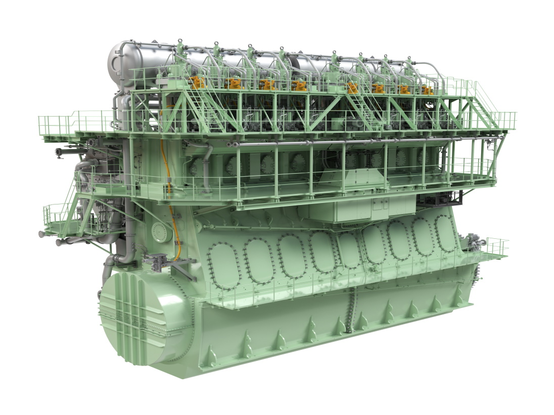
MAN S70ME-C10.5-GI
The MAN S70ME-C10.5-GI is a low‑speed, two‑stroke marine diesel engine with gas injection (ME‑GI) delivering about 10.5 MW, capable of running on heavy fuel oil and natural gas.
Inspector Detail
✓ verified
▸
Designation decoded
S stands for Super-Long-Stroke, 70 for 700 mm bore, ME for electronic control, C10.5 for Mark version 10.5. GI stands for Gas Injection — high-pressure dual-fuel with LNG at 250-350 bar.
Background
The S70ME-C10.5-GI is designed for large container ships (Neo-Panamax class, 12,000-16,000 TEU) and large tankers. The S70 bore size at 700 mm positions it between the S60 (feeder/Panamax) and the S80/G80 (post-Panamax). The GI variant with Mark 10.5 represents the current state of the art for LNG dual-fuel propulsion in this power class.
Calculated metrics
Inspector checklist
- Cylinder liner: 700 mm bore — wear measurement at 8+ points, document ovality and conicity, TDC ring and scavenge port edge as critical zones
- Crosshead bearing: significant piston mass at 700 mm bore — check bearing clearance and surface quality of the guide shoes
- Piston rings: check CPR rings for wear and blow-by, monitor liner-polishing tendency in GI mode
- HCU/FIVA valves: document hydraulic pressure, switching times and leakage rates for each cylinder
- HPS system: check pump performance, accumulator pre-charge pressure and oil quality
- PMI online: compare Pmax and Pcomp values across all cylinders — GI operation should show more even combustion than diesel
- Gas Valve Unit (GVU): block-and-bleed leak test per cylinder
- HP gas compressors: typically 3×50% configuration at S70 power — check vibration, oil analysis, valve plate condition of all units
- Gas injection valves: check nozzle erosion and coking via borescope
- Gas piping: double-wall integrity, annulus HC monitoring, flange gaskets
- Stuffing box: significant piston rod diameter at 700 mm bore — document drainage rates and trend analysis
- Gas injection seals: most critical sealing interface — any leakage requires an immediate gas trip
- Exhaust valve: inspect sealing face and spindle condition
- Turbochargers (TCA series): typically 2 turbochargers at 700 mm bore — check both for equal efficiency
- Scavenge air cooler: pressure differential and cooling performance — fouling increases thermal load on all cylinders
- Auxiliary blower: verify function at low load and during maneuvering
Logbook reference values
| Parameter | Expected | Deviation means |
|---|---|---|
| Exhaust gas temperature after cylinder | 350-420 °C at 85% MCR | Spread >25 °C → gas injection or fuel injection asymmetry |
| HP gas pressure | 250-350 bar upstream of injectors | Pressure drop → check HP compressor or gas piping |
| Pilot fuel share | 2-5% | Rise above 8% → gas injection valve problem, possibly cylinder in diesel-only mode |
| Scavenge Air Pressure | 2.8-3.8 bar abs at MCR | Too low → check turbocharger efficiency or scavenge air cooler |
| Pmax | Per test protocol, typically 155-185 bar | Individual cylinder >5 bar below average → compression deficit |
Common Failure Modes
Expert tips
- 💡 S70 with 2 turbochargers: during slow steaming, one turbocharger can be shut down (TC cut-out) — configure timing and load limits per MAN recommendation, do not change independently
- 💡 For the 3×50% HP compressor configuration: routinely rotate operation across all three compressors to achieve even operating hours — do not always run the same two
- 💡 GI mode and slow steaming: below 25% MCR, GI operation becomes increasingly inefficient — diesel fallback below this limit is economically and operationally sensible
Related components
Classification & regulatory
IMO Tier II standard, Tier III achievable in GI mode without SCR/EGR. IGF Code compliance. Mark 10.5 EEDI Phase 3 compliant. CII rating improvement of approx. 20-25% through LNG GI compared to HFO.
Reference content for inspector orientation. Always verify against manufacturer's manual, latest service letters and class society requirements.
Components & Design
Component data being added…
Technical Data
🤖 Ask about this model
One free question — answered like a marine engineer. No account needed.
Common failures & inspection points
Service & Maintenance
Maintenance per manufacturer manual and classification society requirements. Annual inspection at class survey. Stock spare parts per manufacturer specification.
Suppliers & Spare Parts
Direct links to manufacturer, datasheet, spare-parts portal and dealers — request access below.
📄 Request sourcing links & documentsCases, daily reports, timesheets and AI troubleshooting in the OceanSphere Marine app — free for 14 days.
Start free trial →Find manufacturers, repair shops and spare-part dealers in the Maritime Network — our global company directory.
Maritime Network →